Rivet Nuts - Reduced Countersunk Head with Knurled Shank, Closed Type
This product guide contains the specification for blind rivet nuts with a small countersunk head, round knurled shank and a closed end. These are a stock item available from Westfield Fasteners.
Rivet nuts are installed by inserting the rivet nuts into the correctly sized and shaped hole within the sheet material. The rivet nut is compressed using a pneumatic powered or hand rivet tool, gripping it firmly to the sheet materials. This causes the rivet nuts to compress to form a collar on the blind side of the sheet material. This prevents the nut from being pulled back through the hole and fixes it securely to the sheet material. Like blind rivets, rivet nuts do not require access to the back of the material, so can be used in applications where there is no access to the back of the sheet materials. Features like knurling or the hexagonal shaped shank help to prevent the rivet nut from turning and loosening.
Small countersunk rivet nuts are a specialist version of the full countersunk form, a less commonly required type of rivet nut. With their reduced head height - a smaller head than the full countersunk rivet nuts - these nuts give an almost flush finish where a non-interference fit is not critical. The small countersunk height is ideal for very thin gauge sheet materials, when clamping thin single sheet materials, or when the material is not thick enough for the full countersunk head to be used. This particular type of rivet nut has an end which is closed off.
The knurling and round shank of small countersunk head rivet nuts help to grip to the adjoining surface, and can be used in a multitude of industries, such as aerospace, automotive, rail, HVAC, white goods, electronics, DIY and general engineering.
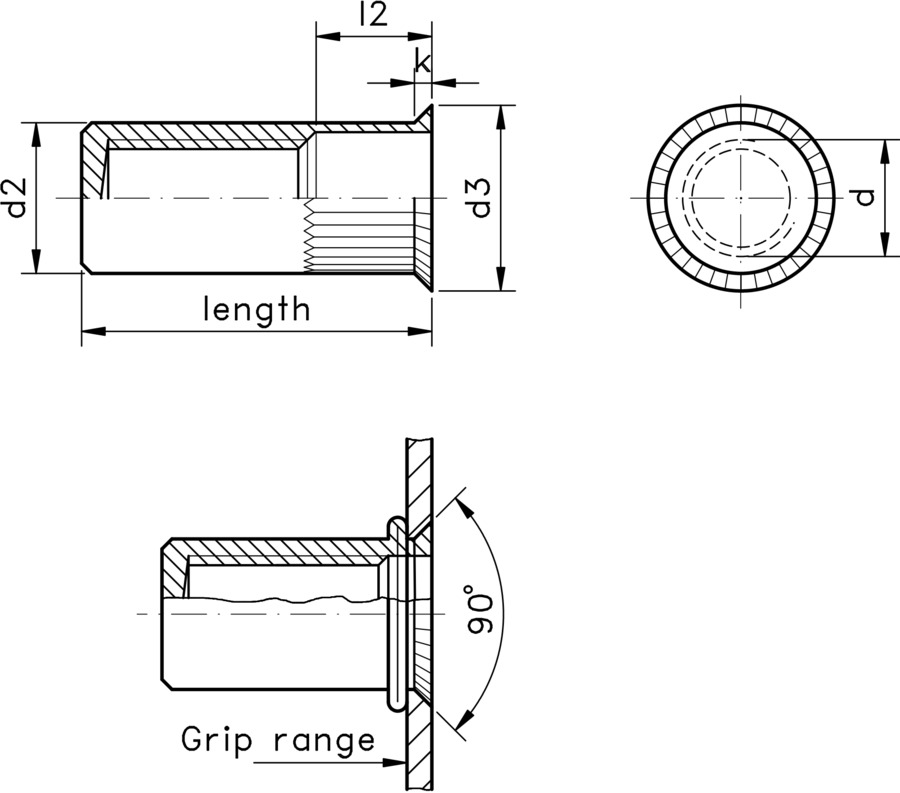
Table 1 below gives dimensions for stainless steel variants in available sizes from M3 to M12, along with information on sheet material thickness, pre-drilled hole sizes and tensile strengths. Table 2 provides similar information for zinc plated steel items.
Please note that the table data below supply typical strength values, head dimensions and overall length, which may vary between batches. Any tightening torque specifications given are guide values depending on the material of the original component and should be checked by testing.