Rivet Nuts - Flat Head with Knurled Shank, Closed Type
This product guide contains the specification for rivet nuts with a flat head, a round knurled shank and a closed end. These are a stock item available from Westfield Fasteners.
Blind rivet nuts are installed by inserting the rivet nuts into the correctly sized and shaped hole within the sheet material. The rivet nut is compressed using a pneumatic powered or hand rivet tool, gripping it firmly to the sheet material.
In the compression process, the thinner walled section without the thread collapses to form a collar on the blind side of the sheet material. This prevents the nut from being pulled back through the hole and fixes it securely to the sheet material.
Like blind rivets, rivet nuts do not require access to the back of the material. Features like knurling, or the hexagonal shaped body within a hexagonal shaped hole, will help to prevent the rivet nut from turning.
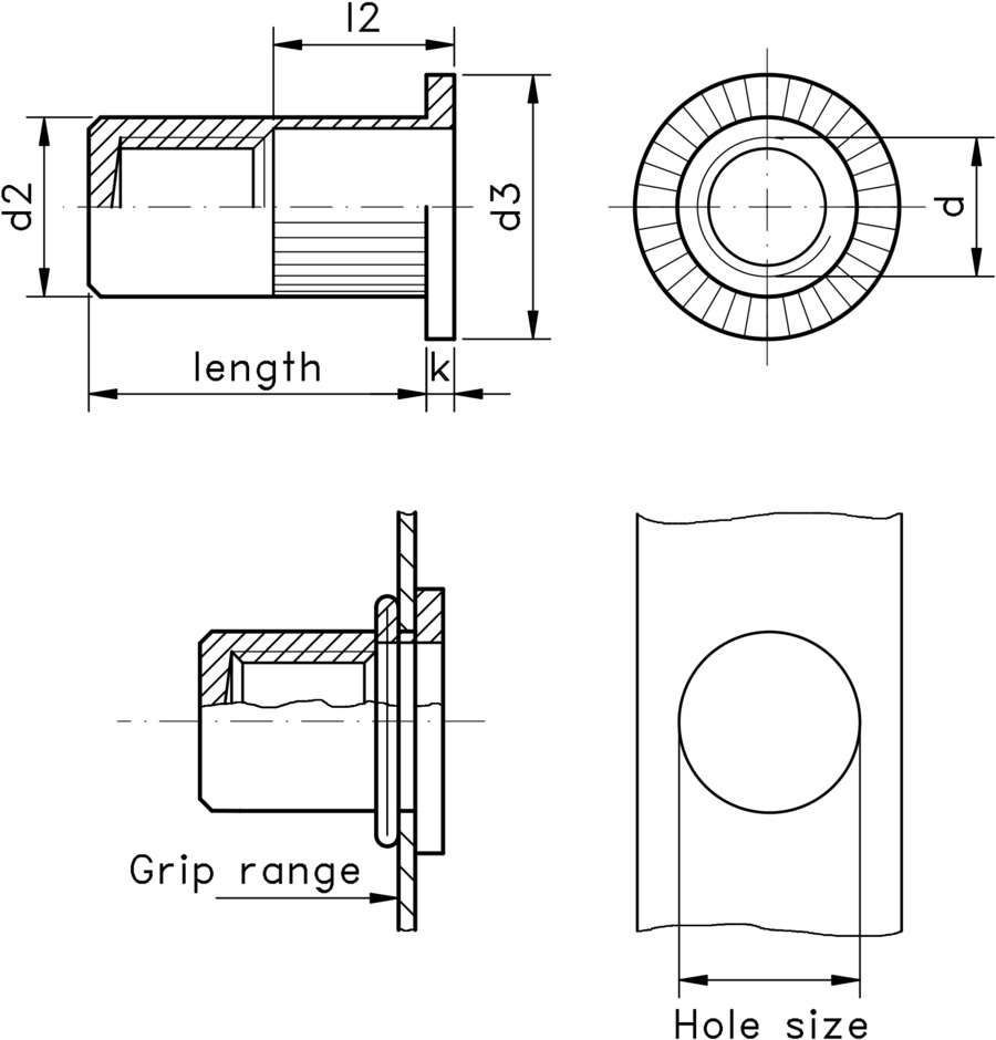
This particular type of rivet nut features a flat head, a round knurled shank and a closed end. The larger diameter of the flat head will spread the load over a greater surface area, making it appropriate for most applications, including connecting soft or brittle materials to a rigid backing.
The knurling/serration helps to grip the nut to the connecting materials and stop it turning. The closed end means that the bolt needs to be a specific length to be used in the rivet nut.
This type of rivet nut is commonly found in white goods and automotive industries.
The data below includes typical strength values.
Table 1 below gives dimensions for stainless steel variants in available sizes from M3 to M12, along with information on sheet material thickness, pre-drilled hole sizes and tensile strengths. Table 2 provides similar information for zinc plated steel items.
Please note that the table data below supply typical strength values, head dimensions, and overall length, which may vary between batches. Any tightening torque specifications given are guide values depending on the material of the original component and should be checked by testing.