
ASME B18.2.2 - UNF Full Hex Nuts
This product guide contains the specification for UNF Full Hex Nuts, a series of standard parts available from Westfield Fasteners. The basis of this specification is the ASME standard ASME B18.2.2.
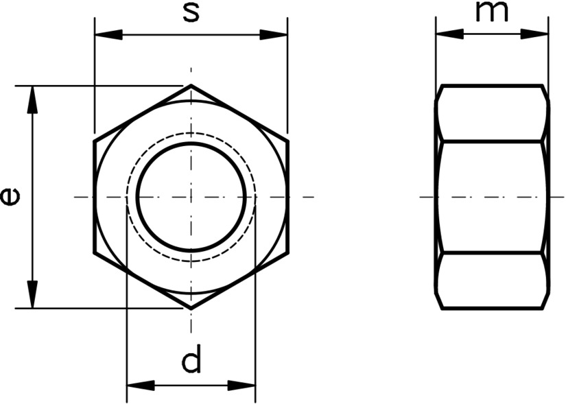
Figure 1: UNF Full Hex Nut
Plain and zinc plated carbon steel variants of these full hex nuts are typically produced to material specification ASTM A563-A. This means that the proof load stress is 90 ksi for plain, uncoated nuts and 68 ksi for zinc plated variants.
Stainless steel items are typically produced to ASTM F594, with the proof load stress beginning at 70ksi, depending on condition.
For brass, the manufacturer can decide on the chemical and mechanical properties of the nuts.
| Nominal Size | Threads Per Inch (TPI) | Basic Major Diameter of Thread, d | Width Across Flats, s | Width Across Corners, e | Thickness, m | |||
|---|---|---|---|---|---|---|---|---|
| min | max | min | max | min | max | |||
| 1/4 | 28 | 0.2500 | 0.428 | 0.438 | 0.488 | 0.505 | 0.212 | 0.226 |
| 5/16 | 24 | 0.3125 | 0.489 | 0.500 | 0.557 | 0.511 | 0.258 | 0.273 |
| 3/8 | 24 | 0.3750 | 0.551 | 0.563 | 0.628 | 0.650 | 0.320 | 0.337 |
| 7/16 | 20 | 0.4375 | 0.675 | 0.688 | 0.768 | 0.794 | 0.365 | 0.385 |
| 1/2 | 20 | 0.5000 | 0.736 | 0.750 | 0.840 | 0.866 | 0.427 | 0.445 |
| 9/16 | 18 | 0.5625 | 0.861 | 0.875 | 0.982 | 1.010 | 0.473 | 0.496 |
| 5/8 | 18 | 0.6250 | 0.922 | 0.938 | 1.051 | 1.083 | 0.535 | 0.559 |
| 3/4 | 16 | 0.7500 | 1.088 | 1.125 | 1.240 | 1.299 | 0.617 | 0.665 |
| 7/8 | 14 | 0.8750 | 1.269 | 1.312 | 1.447 | 1.513 | 0.724 | 0.776 |
| 1 | 12/14 | 1.0000 | 1.450 | 1.500 | 1.653 | 1.732 | 0.831 | 0.887 |
| 1 1/8 | 12 | 1.1250 | 1.631 | 1.688 | 1.859 | 1.949 | 0.939 | 0.999 |
| 1 1/4 | 12 | 1.2500 | 1.812 | 1.875 | 2.066 | 2.165 | 1.030 | 1.094 |
| 1 3/8 | 12 | 1.3750 | 1.994 | 2.062 | 2.273 | 2.382 | 1.138 | 1.206 |
| 1 1/2 | 12 | 1.5000 | 2.175 | 2.250 | 2.480 | 2.598 | 1.245 | 1.317 |